Toolmakers Clamps
I have a couple of toolmakers clamps which I made at school some 50 years ago, they are still working and regularly used but I thought it would be useful to have something smaller. So I scaled down the original and came up with something about two-thirds size. I have included a drawing below but sizes are very flexible. Harold Hall's website has plenty of useful information on toolmakers clamps complete with drawings, suggested sizes and different styles, well worth a look: Workshop Projects - Toolmakers Clamps.
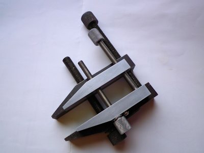
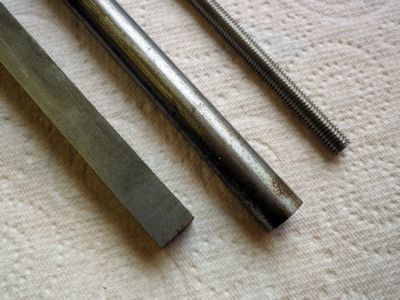
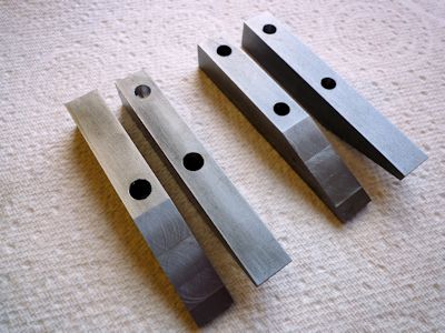
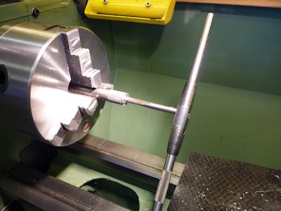
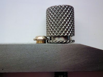
My original toolmakers clamp is shown at (1) with one of the new clamps sitting on top to show the size difference. I had a rummage in the stock to see what I could use without too much machining and made a drawing subsequently using what would have been my preferred sizes. The results of my search (2) consist of a length of 6mm studding (allscrew) stainless steel, a length of 7/16" (11.1mm) square mild steel bar type unknown and a length of 7/16" round mild steel bar for the screw heads. I would have preferred 12mm square but didn′t have any. I decided to make a pair of clamps as one is never enough and there was plenty of material to hand.
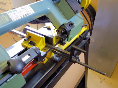

Saw the materials to length, I was making a pair so needed 4 screws and four jaws. I have a small warco bandsaw which makes life easy particularly by using the length stop (3), I allowed a mm for cleaning up the ends. The drawing is at (4) above, click on the image for the full size pdf.
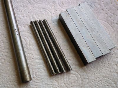
The blanks are shown at (5), four lengths of square for the jaws and four lengths of studding for the screws. I left the bar for the screw heads as found and will just slide it through the 3-jaw chuck on the lathe.
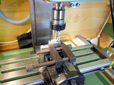
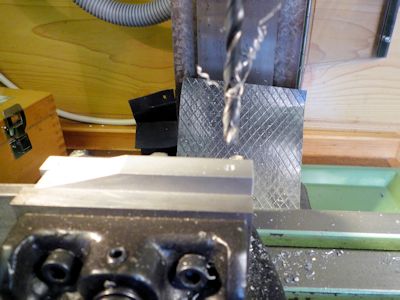
The first job is to clean up and square the ends of the jaws. De-burr the ends before clamping up in the mill vice. I machined all four at the same time. I just rested the ends on the mill table, made sure they were vertical using a square from the vice and clamped up. I used one of my original toolmakers clamps just to make sure nothing moved (6). Machine off just enough to remove the saw marks. Turn the bars over and machine the other end to length.
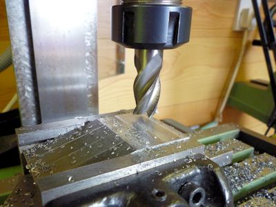
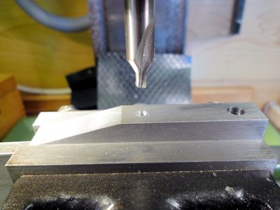
To machine the slope on the jaws I first marked one jaw and scribed an angled line which I used to line up with the top of the mill vice jaw (7). I just lined it up by eye, no fancy angle gauge but you could of course work out the angle (it′s about 17°) and set it more accurately than me. Use packing to raise the rear of the jaws to a suitable height and then line up. I milled all four at one go reasoning that there was plenty of surface area to prevent any slip between the parts.
Once the jaws blanks are to shape the next task is to drill all the holes. As I am making a pair of clamps some sort of jig would be useful to save measuring each jaw separately. In fact it is easy enough just to use the mill vice as a sort of built in jig, or is it a fixture, I never did know the difference! Find a suitable parallel to rest the jaw on. Use a short straight edge to locate the end of the jaw as per photo (8). Once in place the vice can be tightened and the position is repeatable for each new jaw.
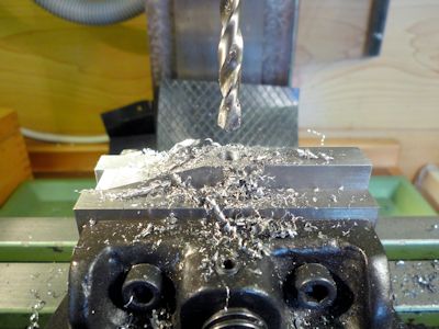
With the first jaw blank in the vice find the front edge (9) using an edge finder. Wind the Y handle to move the table towards you using the dial to move half the diameter of the edge finder plus half the width of the jaw. Once centered lock the Y axis. Repeat the process on the end of the jaw but this time move the table in the X direction half the diameter of the edge finder plus 8mm to position the hole. Use a centre drill or a spotting drill to start the hole for each jaw, I did all four to save changing the drill repeatedly. Drill two jaws from the top and two jaws from the bottom (don′t forget one of the holes is blind).
Once all four are centre drilled, change to a 5mm drill (tapping size for 6mm ISO Metric Coarse thread) (10). Drill two jaws through (don′t forget to remove the packing from under the jaw). Drill two jaws from the bottom to a depth of 4mm. I find that using the ER25 collet chuck to hold the drills is easier than changing to an ordinary drill chuck.
Using the X axis move the table a further 30mm to position the drill for the second set of holes. Following the same procedure centre drill all four jaws (11) this can all be done with the jaws the same way up.
Change to a 6mm drill and drill the two top jaws (the one with the 4mm deep hole) through (12). Change to a 5mm drill and drill the other two jaws. That′s most of the milling and drilling but leave the mill as set it will be needed later to fit the small retaining screw.
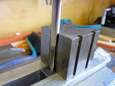
The 5mm holes in two of the jaws require tapping. The ideal method would be to use a tapping and staking tool but I don′t have one, yet! I could of started the threads while still in the mill but it is not easy to get a feel of what is happening with the tap mounted in a chuck so I did it by hand using a small V-block to keep the tap vertical (13). Once the four holes are tapped the jaws are pretty well complete (14) apart from fitting the small retaining screw but this is best done later.
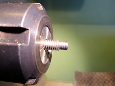
Next for some lathework. It happens that the lathe had the ER25 collet chuck fitted so the next step was to finish the four threaded rods. Face the ends and chamfer, then on two of the rods turn a 6mm long step down to just remove the threads (15) and on this end put on a large chamfer or face at an angle to match the drilled hole. This is the part that fits into the blind hole in the jaw to apply the clamping force.
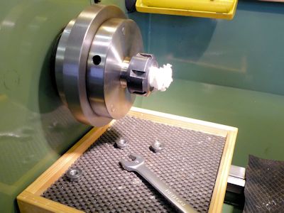
Next job is to change chucks and fit the 3-jaw. This is the job in progress using my chuck board / tool tray, the flanged nuts make the job much easier than using the original nuts and washers (16). I changed chucks because I didn′t think the collet chuck would be man enough for the knurling process which needs a good grip to prevent the part slipping.
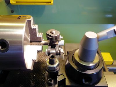
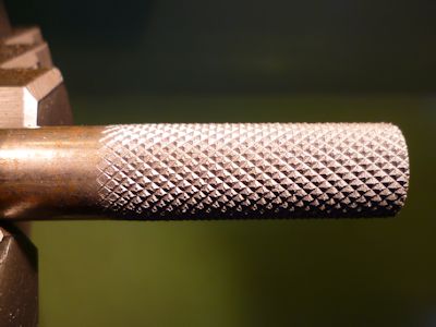
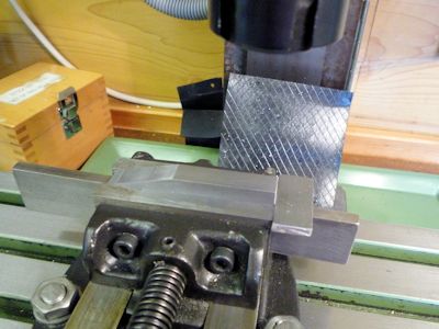
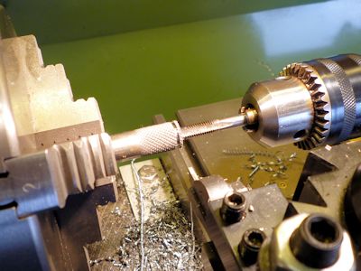
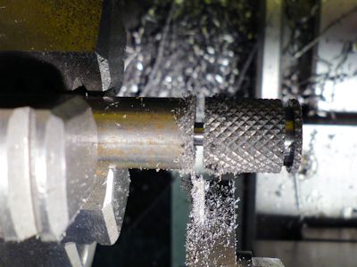
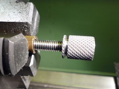
There are many different designs of knurling tools, I have one of the clamp types which is less stressful on the lathe bearings and cross-feed screw. I was going to knurl sufficient length for all 4 screw heads but it would have meant the bar end being some 90mm out from the chuck, so I settled for just doing two at a time. The process is quite straightforward: set the bar in the 3-jaw, open the knurling tool arms to fit over the bar, align the knurl wheels to the centre of the bar, start the lathe at a slow speed and clamp up (17) Slowly advance the knurling tool along the bar. It takes quite a lot of pressure to form the knurl and it may be necessary to make a couple of passes along the bar. I find it a good idea to use copious amounts of WD40 as a lubricant and to wash away any "grindings" that will spoil the pattern if left (flood coolant would be ideal if fitted to your lathe). With a bit of luck the finished knurl should be something like (18), although this could be slightly deeper as there are still small flats on the tops of the diamonds. A good buffing with a brass wire brush helps clean out any remaining dross from the grooves.
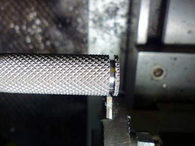
The knurling will have created a large burr on the end of the bar so face off and the use the face to set up for making the groove. Use a parting tool to create the groove, the width isn′t critical, the smallest I had was 1.6mm. Measure the thickness of the parting tool and bring the left hand side up to just touch the faced end of the bar. Use the topslide to move the tool 1mm plus the thickness of the tool towards the headstock. Set a suitable speed and cut the groove about 1.4mm deep (19), the size of the groove depends on the chosen retaining method / screw / fittings. My method was to use a small flat head screw, the conventional approach is to use a sheet brass or steel plate.
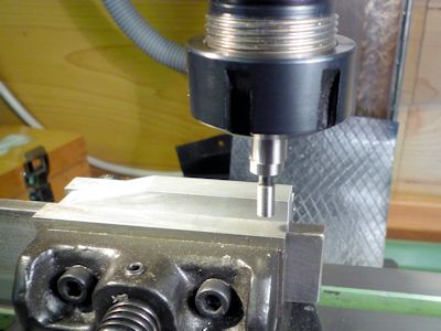
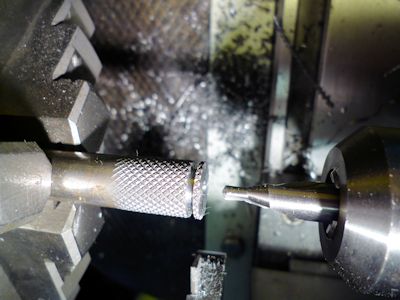
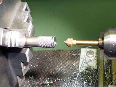
The knurled heads need to screw onto the threaded rods so we need to drill and tap for 6mm ISO Metric Coarse. Centre drill (20) and then drill 5mm to a depth of 12mm.
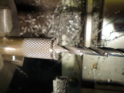
Once the 5mm hole is drilled to depth (21) the hole needs tapping. I started with a 6mm taper tap held in a the tailstock drill chuck to make sure the tap started in line (22). The problem with this is the tap invariably starts to spin in the drill chuck and there is very little feel turning the three jaw by hand as you can′t disengage the drive belts easily.
This is probably not the right way but once the taper tap is in a good way or when it starts slipping in the drill chuck, I used an ordinary tap wrench to finish the job (23). Make sure any tools are removed from the toolpost before doing this or you are likely to find the sharp bit with your hand. Once the taper tap is in all the way change to a plug / bottoming tap to finish off. My plug tap had a long tapered point (something to do with the way they are made) which I ground off so I could thread as close to depth as possible. Once the thread is complete deburr the edge using a countersink or a suitable centre drill (24).
Once the hole is tapped and deburred part off to length (25). Repeat the process for another grooved nut. Then slide the bar out of the chuck knurl and make two plain nuts. Clean out the holes and degrease using meths or some other alcohol. Degrease the threaded rods and assemble with a little Loctite or similar retainer. I held the screws in the bench vice and screwed the heads on as tight as I could by hand, I don′t think they will come apart easily.
Finish off the four clamp screws by general deburring and polishing in the lathe. I used a small length of brass tube with a saw cut along the length to hold the thread part in the 3-jaw (26) to avoid marking the screws. I removed any remaining burrs and put a slight chamfer on all the edges using a fine file. If you don′t like using a file on the lathe just take a fine cut with a suitable lathe tool. If you do use a file make sure it has a properly fitted handle. I also finished off with a bit of abrasive paper to take the sharp points off the diamonds.
All that remains is to find a way of making the front screw captive to the jaw. The classic method is to use a small section of steel or brass strip with a "U" shaped cutout to fit in the screw groove and this is bent and screwed to the jaw. An alternative is to use a small flat or pan head screw. I opted for the second method and found a couple of 3mm screws that had an integral washer (27), these are widely used to fit parts inside computers. I believe they are called "Wheel Rimmed Screws" (might also be called "Pan Washer Head” or “ Washer Head" depending where you are) they are available as hex, slotted or Phillips head. I made a small brass spacer to fit under the head, 3.5mm od 3mm bore and 1.2mm long, this lifts the head just enough to fit into the slot. I did a trial assembly to determine where to drill the hole as this is dependent on the size of the screw head. I had left the mill as last used for drilling the holes so once I had a dimension it was easy to reset the jaw in the chuck and move the X-axis the required distance. I am sure there are other methods to retain the jaw, a stepped spacer secured with a countersunk screw or perhaps remove some threads below the head and use a setscrew through the side of the jaw. It has no need to be particularly robust.
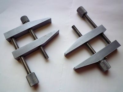
My final efforts are shown at (28). Nothing too complicated, a good starter project and useful as well. It probably took longer to write this web page than it did to make the pair of clamps.