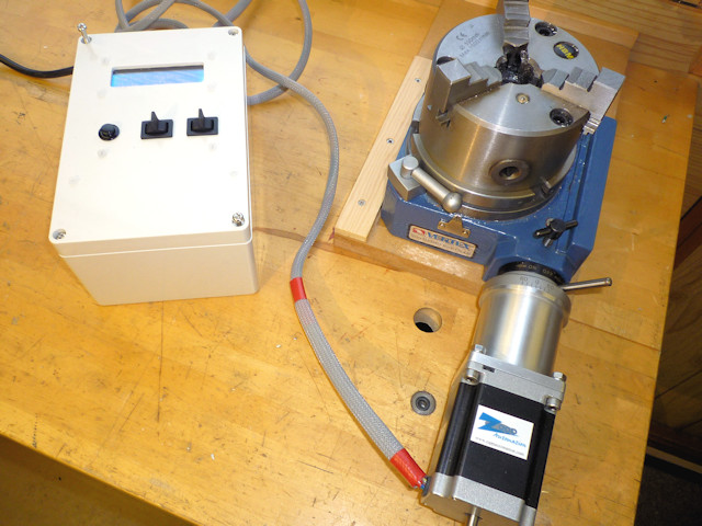
Rotary Table Stepper Drive
I recently read an article in Model Engineers Workshop Magazine (December 2016 issue 249) for adding a stepper motor drive to a rotary table. I don′t use my small Vertex rotary table very often but I thought this might be a useful project to learn a little about stepper motors and digital control of machinery. The article by Carl Wilson describes how to use an Arduino micro-controller to control the rotary division process. Much of the coding is contained in another article in Digital Machinist by Gary Liming. So no original thinking by me here, just a rehash of other engineers good work. All the links and useful information can be found in the Glossary at the end.
The conversion process is in roughly five stages:
- Prepare the rotary table
- Set up the software and program the Arduino
- Machine the enclosure cutouts and assemble the electronics
- Machine the stepper motor mounting
- Assemble and test
Prepping the table can be as simple as doing nothing, a complete strip down and re-build with thrust washers and the like or somewhere in between. There are a few articles on the web giving details (see glossary). Software setup and programming the Arduino is the quickest part and if you use Gary Liming′s software without alteration, the programming takes just a few seconds. Assembling the electronics is mainly about fitting the bits into the box and requires a bit of inginuity to fix things in place. The boards are fairly flimsy and things, like the display, tend not to be square or flat, I found.
The stepper motor mounting I made from three parts and assembled with Loctite and screws. I have no doubt there are other ways of making this or a suitable motor mount could be found ready made and adapted to fit the table. You will probably want to test things as you you go along rather than leave everything to the end. I discovered I had a faulty motor driver, easier to deal with whilst still uncased. I don′t think it makes makes any difference which order things are done.
Rotary Table Preparation
This is covered elsewhere on the web in some detail so I have just made a few notes that may be of interest. Dismantling the table is quite straightforward, just look for allen headed grub screws at the bottom of deep holes. The notes refer to my 4" Vertex table.
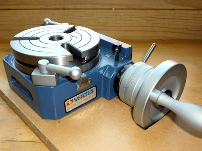

Start off by removing the handle, the table locking clamps and the worm engagement lock. The handle is just one screw but watch out for the shaft key which is small and easily lost. Photo (2) shows the board I made to store the table with a cutout for the handle. The stepper motor will also need a similar storage solution. I used pliers and some cardboard to protect the finish to unscrew the table clamp handles. Remove the engagement lever and collar, two grub screws and it slides off, this is the part that the motor connector will attach to, it has three ready tapped holes for when used with division plates.
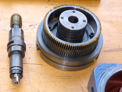
Remove the cam shaft securing and adjusting collar (4), four cap screws. Remove the grub screw that sets the worm engagement depth, found at the bottom of a deep hole (5). The worm shaft and cam bearing can now be removed as one unit, rotate the table and it will push the spindle out.
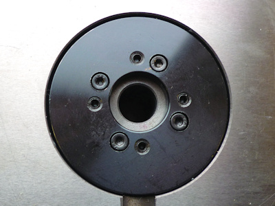
Turn the table upside down and remove the table bearing and adjustment plate (6), four cap screws. The table can now be removed, mine was pretty clean (7) not having been used much, there wasn′t even that much grease. Now that everything is apart it can all be cleaned re-greased and re-assembled. The worm drive shaft can be slid out of the cam adjuster by removing the collar, it is a ground shaft with an oilway and a very good fit in the cam adjuster.
Other than adjustment to remove backlash I didn′t make any changes to my rotary table, it was in fact pretty good before I started. If you have an older well used table it may take a bit more cleaning to remove old grease and any swarf that may have found it′s way inside.
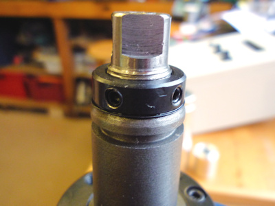
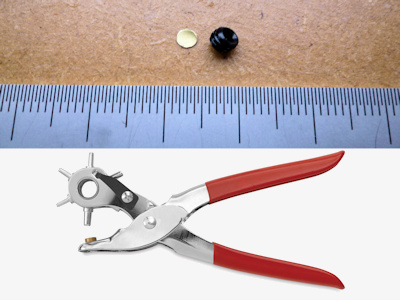
The collar on the worm shaft acts as a thrust bearing and needs to be adjusted so that it is free to rotate but has no end play. You can just make out in photo (8) that there is a washer below it, this is a wave spring washer and provides a bit of tension to restrict the lateral motion. If you tighten the collar too much the shaft will lock up. Once set-up the collar is locked in place with two grub screws. The screws tighten directly onto the threaded portion of the worm shaft, this had caused some damage to the thread which needed cleaning up with a needle file. I made a couple of brass pads from some shim (9) (cut out with a leather punch) to prevent more damage, they are a bit thin but there isn′t room for much more.
Other parts worth note are the cam shaft retainer / bearing (4) and the table retainer / bearing (6). These both feature four cap screws which bolt the item in place and four grub screws which act as jack-screws to prevent clamping the rotating part. When reassembling it is worth adjusting these carefully to limit the table lifting whilst still turning freely and likewise to prevent the cam shaft moving in and out. I noticed with the table bearing / retainer that there was a noticeable stiff spot so it is worth rotating the table through a full 360° whilst adjusting. The cam shaft could be locked in place if you think there is no need to disengage the worm gear. Last bit is to set the worm engagement, this is controlled by a grub screw at the side (5) which engages with a slot in the cam shaft to prevent rotation. If you undo the grub screw and fully engage the worm it will be very difficult to turn, tighten the grub screw just enough so that the worm turns easily with a minimum of backlash.
Program The Arduino Uno
Not much to this really but first you will need to go to the Arduino website and download the Integrated Development Environment (IDE) software. This is basically a fairly lightweight program that runs on your PC (Windows, Mac or Linux) and allows you to edit programs (sketches in Arduino speak) and upload to the Arduino board. You will also need to download Gary Liming′s software. Once the software is downloaded installation is straightforward. The Arduino IDE is self-installing from an exe file in Windows. Gary Liming′s programs come as a zip file which needs un-zipping to a folder. Once unzipped, double click on the "Stepindex23.ino" file and it will start the Arduino IDE and load the program.


All being well you should now have a screen like something like those above. Click on the image to read the text. Affix the LCD shield to the Uno making sure that all the pins are in the right places and none of the connectors is bent. Plug the Uno into the PC using a USB cable, often supplied with the board. The Uno will be powered by the USB connection. First thing to do is go to the "Tools" menu (10) and set the type of board. All being well the software should then report that it is talking to the Uno, bottom right of the IDE, something like "Arduino/Genuino UNO on COM4". You should also be able to click on the "Port" section of the menu to assign a COM port. If this isn′t working and the Port section is greyed out it may be driver related.
If you are using a genuine Uno board (possibly some clones) the USB driver is loaded with the IDE and once the board is selected in the menu everything works. Some copies of the the Uno use a different USB driver chip and the driver needs installing manually (see Glossary for link). Once the correct driver is installed the Port section of the Tools menu should be enabled and you can then select which COM port to use. (Note if you use a different USB port next time around you need to reselect the COM port). Click the upload button to copy the program onto the Uno, thats it. The program will auto-run and briefly display the start-up screen before waiting at the main menu for input. Chances are you won't see anything as the LCD shield contrast probably needs setting, twiddle the multi-turn pot (variable resistor) above the display until the screen comes to life.
Arduino micro-controllers are mainly programmed using the C++ programming language or at least a subset of C++, so the programs are fairly understandable for basic editing. The first few lines of the program (11) are used to set parameters used later. These can be adjusted now, the program is well commented, or left until later when everything is assembled. You may wish to alter gear ratios or even remove some items. There is more help in the readme files that come in the program zip-file. If you are a C++ programmer the world is your oyster, the menu items can be moved around or even removed if you don′t need a particular function. You may wish to experiment with some of the delay timings to help de-bounce the keys but this is probably better done during final testing.
The Case & Electronics
This is like assembling a 3D jigsaw without a picture, I just made a couple of dry runs to see how all the bits will fit into the box! The largest single part is the power supply and if this is going into the box it will pretty well determine where all the other parts fit (you could use an external 12V supply making the control box much smaller). An external power supply could avoid overheating problems but if you put everything in the one box try to leave some airspace around the power supply and stepper driver board.
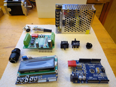
The parts are shown (12) above and are the Arduino Uno, the LCD shield, the cable gland, TB6560 stepper driver, switches, plug, socket and power supply. The circuit boards are all pretty flimsy and the mounting holes are very close to the edges. The LCD shield has a seperate smaller board for the LCD soldered on top and the two boards were not particularly parallel. There is also a multi-turn variable resistor on the board which cunningly sticks up higher than the LCD face. If you are adept with a soldering iron it can be re-positioned on the other side of the PCB. I solved the non-flush pot problem by using a 1.5mm clear polycarbonate sheet between the box lid and LCD with a small cutout for the variable resistor.
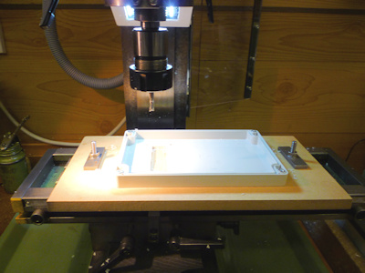
I fitted as much as I could to the box lid, only the mains in and stepper out are fitted to the box. The display needs a cutout in the lid as do the three switches and a number of 3mm holes for various mounting screws. Once I had worked out the position of all the bits I marked the inside of the box lid for the position of the LCD and switch cutouts. I set this up on the mill and used a 5mm slot drill to remove the cutouts, the ABS machines very easily. I fixed the lid to an off-cut of MDF with woodscrews through the mounting holes, I also used double sided tape to make sure nothing moved. A couple of T-nuts and studs fixed the MDF to the mill table (13). With hindsight the double sided tape was overkill, it took me longer to get it off the lid than it did to do the machining. The corners of the switch cutouts I filed square, I drilled the various mounting bolt holes by hand as I did for the other round holes opening them up as necessary with a taper reamer and file.


I used nylon nuts and bolts to fix most of the parts, mainly because I had a pack of 100 and I didn′t have many M3 screws handy. The LCD shield and Uno can be bolted straight to the case front as can the power supply. The motor driver board needs some standoffs to clear the Uno and I made these from ⌀6mm aluminium rod. I also used a short length of ⌀3mm rod inside a plastic tube to support one corner from a spare hole in the Uno board. Once all the PCB′s are in place it just remains to connect the wiring.
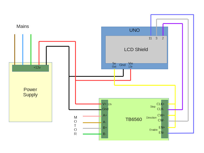
The diagram (16) above shows the inter-connections between the three main parts. Check carefully when soldering to the Uno and the LCD shield as the pins are close together, also check with data sheets that all the wires go to the right places. The diagram does not show the switch leads nor are the board connections in their exact positions (Diagram NOT To Scale). I found it easier to solder a short length of coloured wire to each location on the Uno / LCD shield whilst all the boards were out of the case. I made a note of which colour wire went where and then bolted the boards in place. The wires can then be grouped together, switch leads, control leads and power. I used some cable ties to try and keep things neat(ish) and then trimmed the wires to length ready to connect up. To extend the switches from the LCD shield I soldered a wire to the back of each miniature push button on the board. You need one wire for each switch plus one common wire. I just used a multimeter to find the right solder terminal on the switches.
Stepper Motor Mounting
I have included a drawing that shows how I made the mount, you may need to adjust dimensions to suit the components you have. I used 6082 T6 aluminium ¼" (6.35mm) plate to make the two ends of the connector and a length of 2" x ¼" (50.8MM x 6.35mm) thick wall tube for the middle bit. It is often still easier to get material in imperial sizes, come to that the stepper motor is imperial size as well.
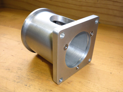

I made the two flat plates and then fitted the motor, flexible coupling and rotary table together to measure the shortest length of tube that would work. The dimensions for the motor mounting plate were copied from the motor spec sheet.
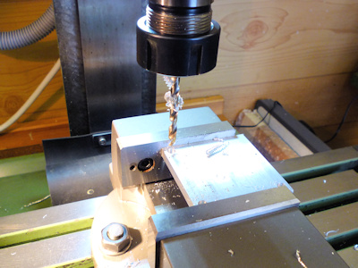
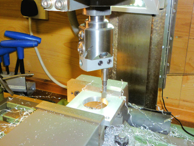
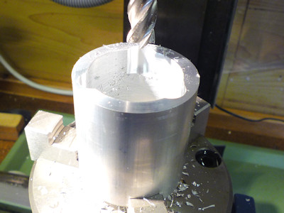
The motor plate is from a length of 3" x ¼" bar, cut to length and then mount flat on parallels in the milling machine vice. Clean up one cut end then reverse and mill to length. Turn 90° clean up the edge reverse and mill to length. With the part still in the vice use an edge finder in X and Y directions to position first hole for drilling use co-ordinate drilling to position the remaining 3 holes (19) and a centre hole (much easier with a DRO, I still count turns). The centre hole will be the motor register. Drill and bore this out to 38.1mm (20) I found the easiest way to check the diameter was using a short length of 1.5" (38.1mm) bar. Strange all the dimensions for the stepper motor are given in mm but they are definitely made with imperial measurements, oh well provided everything fits together!
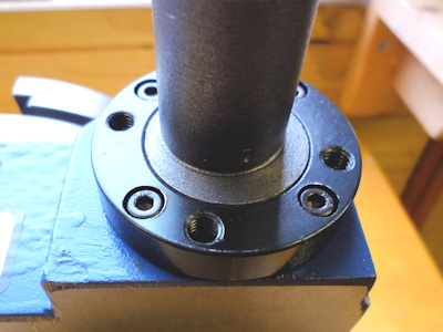
That was the first time I had used the boring head in the mill and I tried to use it to cut the recess for the tube. This didn′t work too well as you can′t really get a flat bottom to the recess. I remounted the plate in the four-jaw chuck on the lathe (21) with the motor register running true and completed the recess, 3mm deep and to suit the tube diameter, with a boring bar.
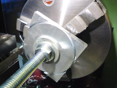
I used another bit of 3" x ¼" bar to turn the plate that bolts to the rotary table. I drilled a 10mm hole in the centre of the plate and used a length of studding to hold it (22). The studding has two nuts locked to it which fit against the back of the chuck jaws and a nut and washer clamp the plate against the front of the jaws, there is a centre in the outboard end of the studding for support. I used a trepanning tool to remove the corners and then turned the O.D. to to size.
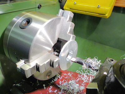
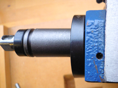
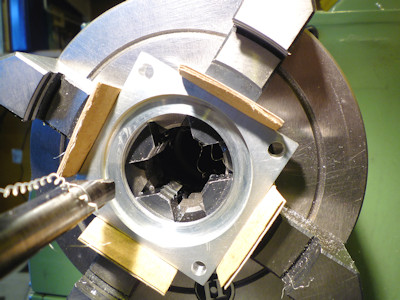
When the R.T. mounting plate is the correct diameter add a step 3mm deep with 38.1mm diameter to create a short spigot to fit the tube bore. Remove from the mandrel (studding) and mount holding the just turned spigot (23), bore out the centre hole to 21mm to fit the R.T. collar. To finish this part it need the three mounting holes drilled to match the table. I clamped the table index ring to the plate, they should be the same diameter, then spotted through with a drill that just cleared the threads in the index ring. Unclamp and drill the holes 5mm, there is no other alignment so keep the holes small, don't use an M5 clearance drill.
The last part to make is the tube that spaces the two plates apart. Cut to just over length and face one end, reverse and face to length. I made my tube 53mm long but you may need to adjust this to accomodate the motor spindle length, the flexible coupling length and the R.T. dimensions. Hit a slight problem here as I used thick wall tube so that I could add some screws to fix the plates on rather than just rely on adhesive. If you are happy just using adhesive a thinner walled tube would work. I found that the bolt heads interfered with the tube (or vice versa) so I had to cut three pockets (24) to clear the heads and allow assembly.
The three parts are "glued" together, I used Loctite 603 which is a high strength oil tolerant retainer. Check alignment before joining, it will depend on the orientation of the holes in the index collar on the R.T. probably easier to join the tube to the table end first and then bolt it in place. The motor mount can then be aligned so that it is square when in use. I had an interesting experience when I first tried assembly. applied the Loctite placed suitable weight on top and left overnight. The following day removed the weight picked it up and it came apart. Apparently Loctite "goes off" still mine was a few years old! If you want to add screws it is probably easier to do this after assembly, I used 3 M3 C/S screws in each end, a bit belt and braces as either screws or adhesive alone will probably do the job.
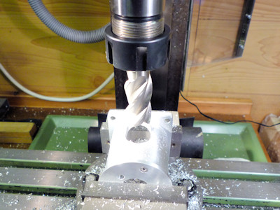
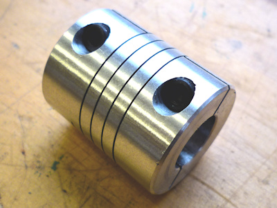
Once the two end plates are in place the slot to access the coupling can be cut (25). In stages starting with an 8mm slot drill, using a 20mm end mill is really pushing this tiny mill! I thought the best place for this was on the underside so that swarf will fall out rather than in. You may need to adjust the slot to suit the fixings in the coupling. I used an aluminium flexible coupling (26) which has both a split collar clamp and a grub screw.
Assemble & Test
Not much to this really, first bolt the connector to the rotary table. Slide in the flexible coupling and tighten onto the table drive, I aligned it so that the grub screw would tighten into the keyway. Fit the motor using four M5 capscews, nuts and shakeproof washers. Tighten the coupling onto the motor shaft and thats the mechanical bit done.
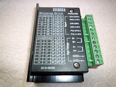
If you have not already done so check and set the switches on the TB6560, I set the current limit to 2A, turn off micro-stepping, set standby current to 50% (the switch positions are printed on the board). Plug the motor lead into the control box DON′T UNPLUG THE MOTOR WHEN POWERED UP! you may well fry the electronics.
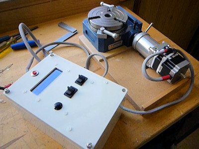
To test I went through each menu item in turn and made sure it did what it was supposed to. I discovered that clockwise and anti-clockwise were reversed but this can be adjusted in the software. I also discovered that I had wired one switch back to front and needed to reverse the leads fortunately just swapping a couple of push on connectors. Found that the motor vibrated rather heavily, haven′t got to the cause of that yet. I also set the table to zero on it′s scale and checked that the angle turned matched what the display said for a full 360° - it did.
With a bit of work on the software, to slow the motor down, I don′t see why the table could not be operated under power, to mill say a semi-circular slot. WIll also need a bit of work on the switch de-bounce software for this to ensure reliability, as it is it is easy to double press keys. Nice little project a good introduction to both the Arduino and to stepper motors neither of which I had used before.
Update - February 2017
Still haven′t solved the vibration problem but whilst trying various options I fitted a new driver module. I tried a unit based on the TB6600 chip which is a slightly newer version than the one originally specified. Not much difference pricewise and looks a bit more like a standard driver. Will also work on higher voltage and deliver more current than the original.

New driver module (27) is enclosed and all the terminals are at one end so I had to do a bit of redesign to fit it in. No problem with the wiring but I had to bend up a bracket from a bit of aluminium sheet to hold it in place. The bracket (28) uses the old fixing holes and is bent to give a bit of room for ventilation of the power supply.
As I had to take everything apart I added a reset button (29) by soldering leads to the back of the shield button in the same way as for the other buttons. Caused me some aggravation as the first button I found in my "bits that will be useful one day box" remained steadfastly open-circuit when pressed, still it was probably 30 years old! Last but not least a short video (30) which shows the table spinning quietly in run mode and then vibrating in step and angle mode. It makes me think this might be software generated as that is the only difference between the modes.
Glossary & Parts List
Model Engineers Workshop Forum - thread discussing the original magazine article and various points arising including some useful information about variations in the Arduino hardware, particularly the LCD shield.
Step Indexer - software download for the original Digital Machinist article. The ZIP file includes three versions of the code and various text notes. The software is, I believe, in the public domain with a GNU licence.
Gary Liming′s Website - describes the making of the original step-indexer which could be used in place of a rotary table and outlines the software in a bit more detail.
British Reaction Research - Carl Wilson′s Blog where he describes steps along the way to creating the original. I counted 13 blog entries which go into some detail of the manufacture. This is a link to the first post.
Arduino Home Page - has all the information about the Arduino project. You can download the IDE (Integrated Development Environment) from here which you will need to program the micro-controller board.
Arduino UNO rev3 Schematic - circuit diagram for the Uno board
Arduino UNO Pinout Diagram - description of the pin functions for the Uno board
CH340G driver - Some boards use the CH340G USB/serial chip as a cheaper alternative to the FTDI chip, this is the driver download link. The FTDI standard driver is installed when you setup the Arduino IDE.
LCD Keypad Shield - information and pinout diagram for the LCD shield. Be aware that different makes of board have slightly different components and working voltages for the keypad resistor chain, see the model engineer discussion thread if your keypad doesn′t seem to work correctly.
Model Engine Maker Forum - thread covering the preparation of a Vertex rotary table ready for automation. This was done by John "Bogstandard" Moore in readiness for the Division Master system but the mechanics are the same.
Stepper Motor Data - This is the specification sheet and wiring diagram for a similar motor to the one I used which is no longer available (2020). Any Nema 23 size motor around the 2Nm holding torque should be quite sufficient indeed a smaller motor may suffice if you have one to hand. My original motor was 8-wire but a 4-wire motor is just as good and will avoid some soldering.
TB6560 Data Sheet - Very basic information on the stepper driver with connections and switch settings.
TB6600 Data Sheet - Connections for the stepper driver with Arduino connections.
| Parts List | |||||
|---|---|---|---|---|---|
| Quantity | Descripion | Part Number | Link | Supplier | Cost |
| 1 | Arduino Uno Rev3 Micro-Controller | UNOR3 | Amazon.co.uk | £8.99 | |
| 1 | LCD Display Shield | SHIELD | " | £5.89 | |
| 1 | TB6560 Stepper Driver Board | TB6560 | " | £7.99 | |
| 1 | TB6600 Stepper Driver Board | TB6600 | " | £6.52 | |
| 1 | 12V 5A Power Supply | 12V5APS | " | £9.39 | |
| 1 | Coupling 6.35mm to 12mm | 635-12C | " | £5.88 | |
| 1 | Enclosure, Abs, Flat Lid | 1554TGY | BOX | Farnell | £14.22 |
| 2 | Switch, SPDT, 6A, Centre Off, Mom | 1818.1302-00 | SWITCH | " | £5.23 |
| 2 | Switch, SPST, 3A, 125v, Solder | R13-502A-05-B | BUTTON | " | £1.28 |
| 1 | Socket, Chassis, Din, Bayonet, 4way | 0107 04 | SOCKET | " | £3.18 |
| 1 | Plug, Free, Din, Bayonet, 4way | 0132 04 | PLUG | " | £3.44 |
| 1 | Cable Gland, K-M, Atex, M16x1.5 | 54115210 | GLAND | " | £1.90 |
| 1 | Sleeving, Braid, 8mm, Grey, 5m | PETGY8BG5 | SLEEVE | " | £4.30 |
| 1 | Nema 23 Stepper Motor | 4.0A/2.2Nm | NEMA23 | Amazon.co.uk | £29.93 |
| 1 | Tube 6082/T6 200mm | 2" x ¼" wall | TUBE | Click Metal | £7.66 |
| 1 | Plate 6082/T6 200mm | 3" x ¼" | PLATE | " | £5.56 |
The list above is for the major parts required for the project. The suppliers are those I used and the prices were correct in January 2017. (Please note the links to some of these items seem to change weekly, apologies if they don′t work) I make no particular recommendation as to the suppliers it is just where I found the bits needed, it is likely that better/cheaper/different parts are available from myriad locations on the web. In addition to the bits listed you will need - hook-up wire, solder, nuts, bolts, spacers, cable ties, crimp connectors and sleeving. Please note that the above table doesn't display well on a small screen, try rotating to landscape to view!
Update 2020
Many of the links in the Glossary and particularly the Parts List table have gone missing over time so I have tried to update them with currently available parts and information. In fact none of the parts are particularly critical and a bit of web searching will find suitable replacements. The Model Engineer Forum link is still active and one of the later additions is the replacement of the switches with a cheaply available numeric keypad. I haven't carried out this mod but it looks quite interesting.
I have also been told that the TB6560 has an inherent quirk, I quote "It may be of interest to you to know these modules apply power to the IC in the wrong order. The manufacturers specification clearly states the 5v logic voltage should be applied and allowed to settle before the higher stepper motor voltage is applied. On these modules the 5v is derived from the (say) 24v supply which compromises the “power-up” sequence and has resulted in “blown” chips." It may therefore be prudent to avoid this and use the TB6600 driver module.