Flip-up Screwcutting Toolholder
If you have to cut metric threads on an imperial lathe or imperial threads on a metric lathe, it is not always possible to use the indicator dial. It is not even possible to cut all pitches of metric threads on a metric lathe unless you have multiple gears for the threading dial indicator. This means keeping the half-nuts permanently engaged on the lead-screw and putting on a cut and then undoing the cut and reversing the lathe. It is easy to make a mistake especially if you don′t cut threads very often. This tool-holder overcomes this by avoiding the necessity to remove the cut at the end of a pass.
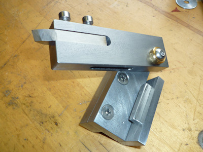
Not an original idea of mine as I have seen it in a couple of places on the internet. This is my version of a flip-up toolholder. In use this tool does what it says, at the end of a cut you just stop the lathe switch into reverse and as the tool runs back it "flips" up to clear the just cut thread. Once back to the start the tool drops down ready for the next cut to be put on. Repeat as necessary until the thread is at full depth. The only caveat is that the lathe has reverse drive.
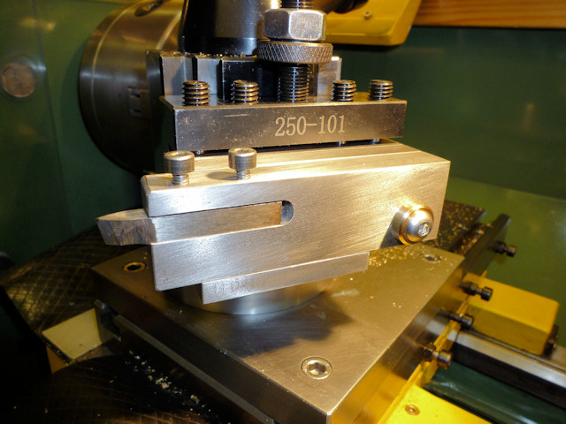
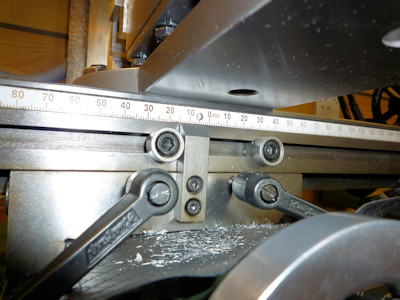
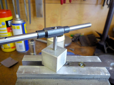
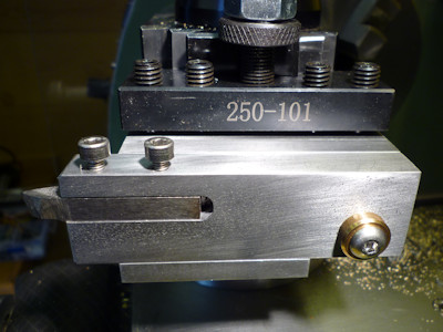
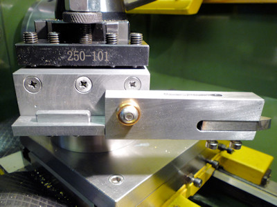
The toolholder is made from stock bar and the dimensions are not critical. I used what I had to hand which was mostly old imperial stock with a few metric screws to hold everything together. I made the toolholder from discrete parts but you could mill the body from one chunk if you have the capacity and time. I made this to work with my QCTP as shown above (1), so the only really important measurement is to make sure that the tool ends up on centre height. I made the holder to use an old ¼" HSS tool but it could be made to take a carbide insert.
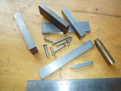
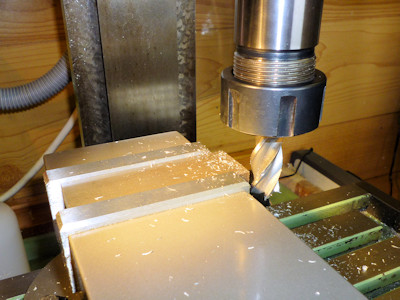
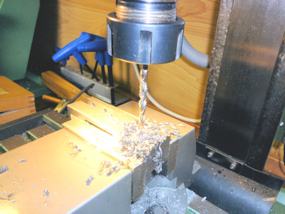
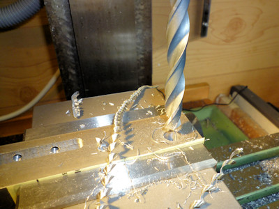
I measured up one of my toolholders for the QCTP and found a bit of HSS that could be easily re-purposed for the "sharp end". Once sure that every thing would work I cut the BMS bar to length with a bit of machining allowance (2). Firstly check that the mill vice is set parallel to the table as all the parts are milled and drilled in the vice. I machined all the major parts to length before doing anything more complicated. Support the bar on parallels and clean up one cut end (3), reverse the bar and bring to length. There are only 6 parts to make with 11 assorted screws so the toolholder doesn′t take too long to construct.

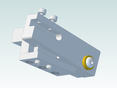
Working from a rough sketch isn′t necessarily a good idea especially relying on my rusty maths skills! Measuring and making on the fly resulted in a non-optimal placement of the key which I thought ended up too far back. The toolholder still works well but I made a proper drawing with the key better placed, click on the image (4) above for the PDF version of MkII. The drawing at (5) is a view from underneath the toolholder showing how the key fits into the swing arm. As can be seen the nearer the front the key is the better it will prevent any tendancy for the swing arm to move sideways. Just a reminder that this is being made for the WM250 with an AXA style QCTP 100 size so suitable for most 5" centre height lathes.
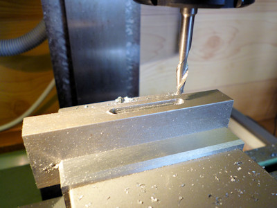
The arm was the first piece made as it had most machining. I was a bit worried about the key slot as the only suitable slot drill I had was a bit worn and by the look of it a long reach version, a recipe for a broken cutter. Set the arm on parallels in the vice and use an edge finder to locate the centre of the bar. Similarly use the edge finder to locate the end and wind the X-axis handle to set the start of the slot. Set the table stop (6), wind to the other end of the slot and set the other table stop. The stop bar on my WM14 mill is fairly flimsy so approach gently and stop winding when you can just feel the stop. I took the cutting fairly gently (7) and it was alright until I got about 2mm deep when it become noticeable that the slot drill was re-cutting the chips. You can feel it and hear it - crunchy! Flood coolant or a good air blast would be useful. I had neither and the best I could do was to use my air-brush compressor which had just enough puff to blow the chips out of the slot. The finish on the inside of the slot wasn′t the best but it was a good fit on the bit of bar I had selected for the key.
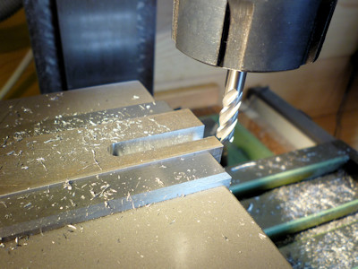
With the swing arm set flat on parallels in the mill vice mill the slot for the tool. I used a 6mm end mill for this, a bit easier as the slot is open ended. I still had to use the air-brush compressor to blow the chips away. The slot is on the top edge of the swing arm so check that you are working on the correct end i.e. the slot needs to be top, left, front and the same end as the key slot when the swing arm is on the lathe. Turn the swing arm upright and drill the two tapping size holes for the tool clamping screws. As you can see I use the ER25 chuck to hold the drill, it saves changing chucks all the time.
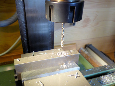
The last operation on the swing arm is to drill the hole to take the "top hat" bearing. This needs to be drilled at the same time as the hole in the back plate so that the bottom of the swing arm aligns with the bottom of the back plate. Clamp both parts in the mill vice at the same time. They are the same width (25mm) but BMS bar isn′t that accurate so a piece of paper against the vice jaw (10) will take up any irregularities and make sure that both parts are clamped firmly. Drill through both parts with an M5 tapping size drill. Separate the parts and drill through just the swing arm (11) 8mm to take the bearing. You could ream the 8mm hole but the bearing has to be turned so can be made to fit.
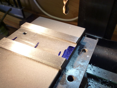
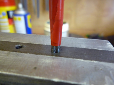
The back plate is next on the agenda and this is just drilling and tapping various holes. I haven′t taken any photos as drilling one hole looks much the same as another. The back plate already has one hole in for the pivot screw, which can be can be tapped M5 (12) in the bench vice, start the tap in the mill to get it square. The back plate needs 3 holes drilled and countersunk for the M5 screws that fix it to the clamping block. I just drilled 5mm as I find this clears an M5 screw quite comfortably. The countersinks need to be quite deep to make sure the screws finish below the surface, otherwise they might catch the swing arm. I was surprised that I stalled the mill cutting these as I was nearly down to depth. It may have been better to use cap screws in counterbores. Check the countersinks are deep enough before removing from the mill.
The clamping block could be made now to use the same settings on the mill. It is just a 75mm length of 13mm square bar with 3 x M5 tapped holes in it to match the back plate. Once made check it fits and put it aside until later, it is not really needed until final assembly time.
The back plate also needs 3 holes 11mm deep tapped M4 on it′s underside to locate the stop plate. Using a parallel (13) across the end of the vice jaws and working from the fixed jaw it is easy to locate the set of 3 holes in the back plate and the stop plate without too much setting up. That is set the spindle axis on the centre of the back plate (nominally 5mm from the fixed jaw) set the spindle axis 8mm from the end. Drill first hole M5 tapping size, move 17mm drill second hole, move 17mm drill last hole. Wind the table back to starting point and put the stop plate in the vice and line it up as above and it is ready to drill the clearance holes at the same locations.
Once the holes in the under edge of the back plate have been drilled they need to be tapped M4. I did this in the bench vice using a tapping block (14) to keep the tap straight, just a bit of aluminium with a hole to fit the tap shank. These are blind holes drilled 11mm deep. To avoid the tap hitting the bottom of the hole I wrap a bit of tape around it about 10mm from the end (15) now I know when the tap is nearing the bottom of the hole. It doesn′t really need to be this deep, the strength doesn′t increase much beyond 6mm in theory.
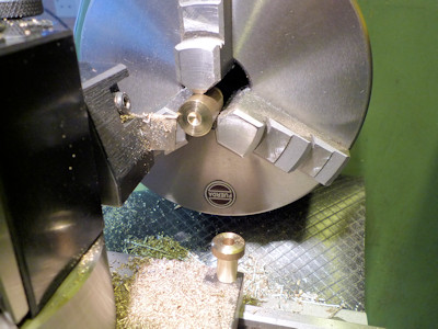
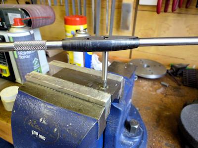
Before you can fit the key to the stop plate you need to partially assemble the toolholder and you will need the "top hat" bearing (18). This a a straight forward turning job. Set a length of 13mm bar in the three jaw chuck or collet and face to give a clean end. Turn down to 8mm diameter for a length of 13mm. I made it slightly too long and used the extra length to test fit into the hole in the swing arm, it needs to be a good fit. The arm rotates around the brass and the bearing is clamped firmly to the back plate. Face the bearing to be the same length as the swing arm is thick plus about 0.01mm, The fit being such that when the bearing is screwed home the swing arm is held as close as possible to the back plate without binding. Once happy that the fit is right for length and diameter, drill through 5mm for the fixing bolt and then part off to give a 3mm thick "rim" to the "top hat". Reverse in the chuck and face off and chamfer.
Once the stop plate is drilled it can be screwed to the back plate with 3 M4 countersunk screws (you could use cap head allen bolts but I used what was available). Assemble the swing arm to the backplate with the bearing in place. All being well the arm shold be free to move up and down with no lateral movement. The arm should rest on the stop plate along it′s length.
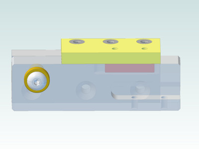
Cut a piece of bar for the key so that it is longer than the finished 25mm but still fits into the slot in the swing arm without sliding back and forth. If the slot is 7mm deep make the key piece 7.3mm high or thereabouts. Drop the swing arm down and it should clamp the key between the arm and the stop. Clamp the assembly in the mill vice with the stop plate on top and the back plate on a parallel. The key piece should now be clamped firmly in place something like the drawing (17) but filling the slot. The key is highlighted red and I have made the arm semi-transparent.
Using the front and side of the stop plate as reference set the mill and drill two M3 tapping size holes through the stop plate and right through the key. It will mark the bottom of the slot in the swing arm but no one will see it. Unclamp and remove the key which can now be made the correct length, it needs to be shorter to miss the ends of the slot. Tap the two holes in the key M3. Drill the stop plate through 3mm for the two clamping bolts. I used two cap head bolts to secure the key to the stop plate. Remove the stop plate from the back plate and mount in the mill vice with the key uppermost. Mill off the top of the key and the bolts to 6mm high. Clean up the key and put a chamfer all the way around the top to help guide it into the slot. The photo at (18) shows my version and you can see that the key is some way back from the edge, the drawing makes it a lot closer to the front.
Reassemble the toolpost making sure that all the screws are really tight, you could use a retainer on the threads but I don′t think it is necessary. During assembly make sure that the swing arm is free to move and that it re-locates on the key without any sticking or rubbing, it must drop down freely under its own weight. Don′t oil anything it will just help any swarf to stick where it shouldn′t. Clean up and add chamfers as you require, it would look quite good blackened to match the QCTP!
In use it works well, it shows no tendancy to move sideways and flips up easily for the return journey. It doesn′t really flip up that much. It actually very slightly retracts the tool as it flips because the pivot point is below the cutting edge. It is of course important to set the tool on centre height. In my limited testing I didn′t notice any swarf getting into the works but if it does it is easy to flip the arm all the way over (20) and clean it out. Also useful to move the tool out of the way to inspect the thread or to run a chaser / die down it to clean up. Just remember the sharp bit is pointing at you though.

I made a short video (21) of the toolholder in action. Unfortunately the auto-focus on the camera prefered to focus on the QCTP but you can still see how the toolholder works. This is cutting an M12 thread in aluminium. The nut fitted without using a die or chaser but there are a few small burrs on the thread crests, nothing that can′t be removed with a bit of green abrasive pad. The end result (22) isn′t too bad and might be improved by using the top-slide at an angle when cutting the thread.
Links To Other Similar Tools
Home Model Engine Machinist - thread discussing the use of threading dials on a metric lathe but with some pictures of flip-up tool holders. This is what prompted me to make this item
Model Engine Maker - thread covering the design and making of a suspiciously similar flip-up tool post by John "Bogstandard" Moore